The Electronics
Various deviations were made upon completing the initial prototype build early in Senior Design II. Upon completion of the first batch of code and the first PCB, several issues were noted and resolved. The notes of such changes are listed in this section, along with commentary regarding the requisite changes. There were also several connections to the microcontroller that needed to be made that were not made. These connections were prescribed by the data sheet that were missed on the first rev. These changes were not necessary upon further inspection, but were recommended so it was decided to make them in board two. Along with the changes that were made according to the various microcontroller pins, there was also a mistake in the wiring from the Bluetooth module to the microcontroller, which was fixed rather quickly.
Schematic and PCB Design
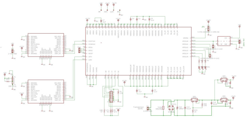
The schematic is shown as follows, which as discussed above has various deviations, most notably the removal of the various headers that were initially intended to supply the LED matrix, but it was decided after rev 1 to simply have the 5V supply directly feed the matrix. The schematic also includes the new level converter, which is valuable in converting the 3.3V to 5V quickly. This was initially a problem where the standard level converter with MOSFETs was giving us some issues, the TI solution rectified the problem immediately.
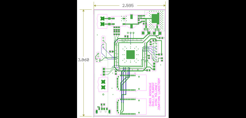
Lastly, the board layout reflects the changes in the schematic, the relative size remains the same while adding several features. The second Bluetooth module can be found under the first Bluetooth module, and the headers are removed from the perimeter of the board, making the overall size thinner.
Power Supply Design
Primarily, the major concern from a hardware standpoint was a problem with heat dissipation. In the first board rev, the decision was naively made to step the DC voltage down after regulation from 28VDC down to 6VDC. This was a bad choice, simply due to pure power dissipation in the regulator. As can be seen in the calculations made in the final presentation given for the conclusion of Senior Design II. The basic power calculations in the old rev lead to a dissipation of 11.4W, which results in a whopping 57 degree Celsius increase in temperature. This was far too hot, and actually led to regulator shutdowns as well as a scathingly hot regulator.
If I were to restart the project at this time, there are a few changes that could be changed in order to rectify several problems that we had as a team. First of all, the 5V power supply is strong enough to supply both the LED matrix as well as the micro and Bluetooth modules. In the current revision, it is set up so that the power supplies are separated and a 5V supply enters the supply separately through a completely different header. This problem could be simplified by just using the 5V header for everything. This also removes the heat problem of the regulator in the system. It actually removes the problem regulator entirely; the 3.3V and 1.2V regulator is more than enough.
Other problems that were addressed through the course of the semester that I would re implement include bypassing the board with the 5V supply for everything but level conversion. The board still needs the 5V for communication, but any power that runs to the LED matrix needs to run direct to the matrix.
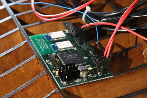
Gallery